For the images, the following were used:
a) A 5×5 square
b) A triangle, base = 4 boxes, height = 3 boxes
c) A hollow 10×10 square, 2 boxes thick
d) A plus sign, one box thick, 5 boxes along each line.
For the strels, the following were used:
a) 2×2 ones
b) 1×2 ones
c) 2×1 ones
d) A diagonal line, two boxes long.
e) A cross, 3 pixels long, one pixel thick.
The binary images and strels that will be used are shown in figures 1 and 2, respectively. Note that pixels with 0 value are treated as background, and pixels with value of 1 are foreground.
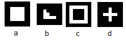
Figure 1. Binary images used to demonstrate erosion and dilation.

Figure 2. Structuring elements used.
The effect of dilation and erosion were predicted. With the use of a graphing paper, the results were hand-drawn. Dilation works by gliding the origin of the strel on the image. On points where the strel exceeds the image, the pixel value will be 1. For erosion, the opposite happens. On points where the strel exceeds the image, the pixel where the origin of the strel is will have a value of 0. This was also done on Scilab to compare if the hand-drawn results are correct. The functions dilate() and erode() were used. The origin was defined to be at the center of the structuring elements. For a 2x2 elements or those that can fit in a 2x2,the origin was defined at the [1,1] element and if that pixel is blank then [2,1] was chosen. Note that the legend ( a), b), c)...) corresponds to the strels applied onto the image. Figures 3-10 shows the hand-drawn and the corresponding results using Scilab. For the dilation, the shaded part represents the pixels that are added to the image, or the pixels that will have a value of 1. For erosion, the shaded part corresponds to the eroded part, or the pixels will have a value of 0.

Figure 3. Dilation of the 5x5 binary image.

Figure 4. Dilation of a triangle with a height equal to 3 pixels and a base
of 4 pixels.
 Figure 5. Dilation of a hollow 10×10 square with thickness of two pixels.


of 4 pixels.


It can be seen that the hand-drawn results matched the results from Scilab. Great! :)
To answer the question in the manual, the thin() function in Scilab performs "thinning" of binary objects. The resulting skeleton is not always connected and is very sensible to noise [1]. The skel() function, on the other hand, performs skeletonization that can be further "thinned" by thresholding the output image. In addition, the resulting image is always connected [1].
Since all the required outputs are correct, I would give myself a grade of 10/10. I would like to thank Joseph Raphael Bunao for helping me understand the dilate() and erode() functions in Scilab.
Reference:
[1] Built-in help function in Scilab.
No comments:
Post a Comment